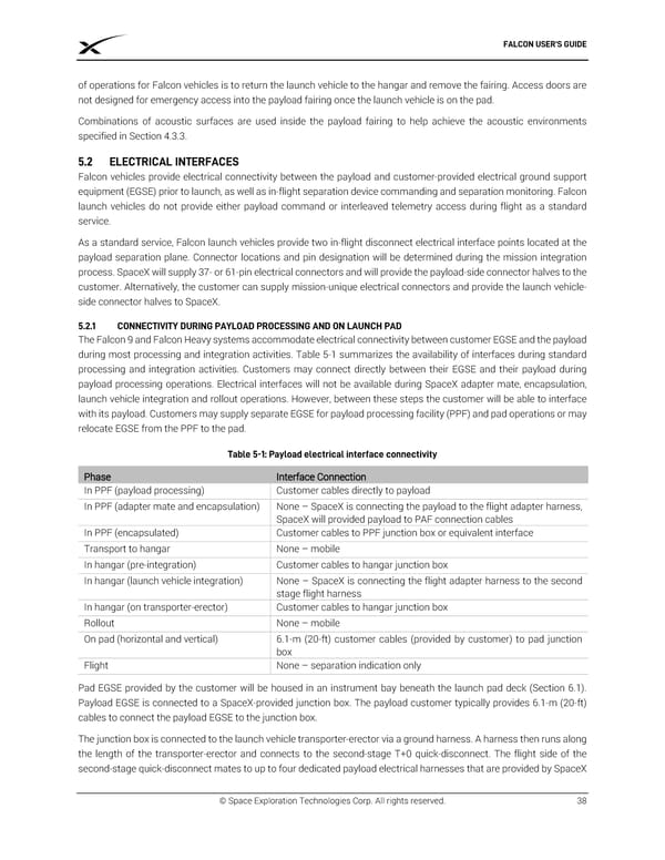
FALCON USER’S GUIDE of operations for Falcon vehicles is to return the launch vehicle to the hangar and remove the fairing. Access doors are not designed for emergency access into the payload fairing once the launch vehicle is on the pad. Combinations of acoustic surfaces are used inside the payload fairing to help achieve the acoustic environments specified in Section 4.3.3. ELECTRICAL INTERFACES Falcon vehicles provide electrical connectivity between the payload and customer-provided electrical ground support equipment (EGSE) prior to launch, as well as in-flight separation device commanding and separation monitoring. Falcon launch vehicles do not provide either payload command or interleaved telemetry access during flight as a standard service. As a standard service, Falcon launch vehicles provide two in-flight disconnect electrical interface points located at the payload separation plane. Connector locations and pin designation will be determined during the mission integration process. SpaceX will supply 37- or 61-pin electrical connectors and will provide the payload-side connector halves to the customer. Alternatively, the customer can supply mission-unique electrical connectors and provide the launch vehicle- side connector halves to SpaceX. 5.2.1 CONNECTIVITY DURING PAYLOAD PROCESSING AND ON LAUNCH PAD The Falcon 9 and Falcon Heavy systems accommodate electrical connectivity between customer EGSE and the payload during most processing and integration activities. Table 5-1 summarizes the availability of interfaces during standard processing and integration activities. Customers may connect directly between their EGSE and their payload during payload processing operations. Electrical interfaces will not be available during SpaceX adapter mate, encapsulation, launch vehicle integration and rollout operations. However, between these steps the customer will be able to interface with its payload. Customers may supply separate EGSE for payload processing facility (PPF) and pad operations or may relocate EGSE from the PPF to the pad. Table 5-1: Payload electrical interface connectivity Phase Interface Connection In PPF (payload processing) Customer cables directly to payload In PPF (adapter mate and encapsulation) None – SpaceX is connecting the payload to the flight adapter harness, SpaceX will provided payload to PAF connection cables In PPF (encapsulated) Customer cables to PPF junction box or equivalent interface Transport to hangar None – mobile In hangar (pre-integration) Customer cables to hangar junction box In hangar (launch vehicle integration) None – SpaceX is connecting the flight adapter harness to the second stage flight harness In hangar (on transporter-erector) Customer cables to hangar junction box Rollout None – mobile On pad (horizontal and vertical) 6.1-m (20-ft) customer cables (provided by customer) to pad junction box Flight None – separation indication only Pad EGSE provided by the customer will be housed in an instrument bay beneath the launch pad deck (Section 6.1). Payload EGSE is connected to a SpaceX-provided junction box. The payload customer typically provides 6.1-m (20-ft) cables to connect the payload EGSE to the junction box. The junction box is connected to the launch vehicle transporter-erector via a ground harness. A harness then runs along the length of the transporter-erector and connects to the second-stage T+0 quick-disconnect. The flight side of the second-stage quick-disconnect mates to up to four dedicated payload electrical harnesses that are provided by SpaceX © Space Exploration Technologies Corp. All rights reserved. 38
 SPACEX FALCON USER’S GUIDE Page 41 Page 43