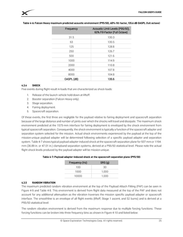
FALCON USER’S GUIDE Table 4-6: Falcon Heavy maximum predicted acoustic environment (P95/50), 60% fill-factor, 135.6 dB OASPL (full octave) Frequency Acoustic Limit Levels (P95/50), 60% Fill-Factor (Full Octave) 31.5 130.3 63 130.5 125 128.8 250 126.7 500 121.6 1000 114.9 2000 110.8 4000 107.8 8000 104.8 OASPL (dB) 135.6 4.3.4 SHOCK Five events during flight result in loads that are characterized as shock loads: 1. Release of the launch vehicle hold-down at liftoff. 2. Booster separation (Falcon Heavy only). 3. Stage separation. 4. Fairing deployment. 5. Spacecraft separation. Of these events, the first three are negligible for the payload relative to fairing deployment and spacecraft separation because of the large distance and number of joints over which the shocks will travel and dissipate. The maximum shock environment predicted at the 1575-mm interface for fairing deployment is enveloped by the shock environment from typical spacecraft separation. Consequently, the shock environment is typically a function of the spacecraft adapter and separation system selected for the mission. Actual shock environments experienced by the payload at the top of the mission-unique payload adapter will be determined following selection of a specific payload adapter and separation system. Table 4-7 shows typical payload adapter-induced shock at the spacecraft separation plane for 937-mm or 1194- mm (36.89 in. or 47.01 in.) clampband separation systems, derived at a P95/50 statistical level. Please note the actual flight shock levels produced by the payload adapter will be mission-unique. Table 4-7: Payload adapter-induced shock at the spacecraft separation plane (P95/50) Frequency (Hz) SRS (g) 100 30 1000 1,000 10000 1,000 4.3.5 RANDOM VIBRATION The maximum predicted random vibration environment at the top of the Payload Attach Fitting (PAF) can be seen in Figure 4-9 and Table 4-8. This environment is derived from flight data measured at the top of the PAF and does not account for any additional attenuation as the vibration traverses the mission specific payload adapter or spacecraft interface. The smoothline is an envelope of all flight events (liftoff, Stage 1 ascent, and S2 burns) and is derived at a P95/50 statistical level. The random vibration environment is derived from the maximum response due to multiple forcing functions. These forcing functions can be broken into three frequency bins as shown in Figure 4-10 and listed below: © Space Exploration Technologies Corp. All rights reserved. 25
 SPACEX FALCON USER’S GUIDE Page 28 Page 30