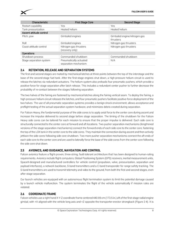
FALCON USER’S GUIDE Characteristic First Stage Core Second Stage Restart capability Yes Yes Tank pressurization Heated helium Heated helium Ascent attitude control Pitch, yaw Gimbaled engines Gimbaled engine/nitrogen gas thrusters Roll Gimbaled engines Nitrogen gas thrusters Coast attitude control Nitrogen gas thrusters Nitrogen gas thrusters (recovery only) Operations Shutdown process Commanded shutdown Commanded shutdown Stage separation system Pneumatically actuated N/A separation mechanism RETENTION, RELEASE AND SEPARATION SYSTEMS The first and second stages are mated by mechanical latches at three points between the top of the interstage and the base of the second-stage fuel tank. After the first-stage engines shut down, a high-pressure helium circuit is used to release the latches via redundant actuators. The helium system also preloads four pneumatic pushers, which provide a positive-force for stage separation after latch release. This includes a redundant center pusher to further decrease the probability of re-contact between the stages following separation. The two halves of the fairing are fastened by mechanical latches along the fairing vertical seam. To deploy the fairing, a high-pressure helium circuit releases the latches, and four pneumatic pushers facilitate positive-force deployment of the two halves. The use of all-pneumatic separation systems provides a benign shock environment, allows acceptance and preflight testing of the actual separation system hardware, and minimizes debris created during separation. For Falcon Heavy, the fundamental purpose of the side cores is to apply axial force to the center core during ascent and increase the impulse delivered to second stage before stage separation. The timing of the shutdown for the Falcon Heavy side cores can be tailored for each mission to ensure that the proper impulse is delivered. Each side core is structurally connected to the center core at forward and aft locations. Two pusher separation mechanisms (lengthened versions of the stage separation mechanisms) connect the forward ends of each side core to the center core, fastening the top of the LOX tank in the center core to the side cores. They maintain the connection during ascent and then actively jettison the side cores following side core shutdown. Two more pusher separation mechanisms connect the aft ends of each side core to the center core and are used to laterally force the base of the side cores from the center core following the side core shut down. AVIONICS, AND GUIDANCE, NAVIGATION AND CONTROL Falcon avionics feature a flight-proven, three-string, fault-tolerant architecture that has been designed to human-rating requirements. Avionics include flight computers, Global Positioning System (GPS) receivers, inertial measurement units, SpaceX-designed and manufactured controllers for vehicle control (propulsion, valve, pressurization, separation and payload interfaces), a network backbone, S-band transmitters and a C-band transponder for range safety tracking. The S-band transmitters are used to transmit telemetry and video to the ground, from both the first and second stages, even after stage separation. Our launch vehicles are equipped with an autonomous flight termination system to limit the potential damage caused by a launch vehicle malfunction. The system terminates the flight of the vehicle automatically if mission rules are violated. COORDINATE FRAME Falcon vehicles use a right-hand X-Y-Z coordinate frame centered 440.69 cm (173.5 in.) aft of the first-stage radial engine gimbal, with +X aligned with the vehicle long axis and +Z opposite the transporter-erector strongback (Figure 2-4). X is © Space Exploration Technologies Corp. All rights reserved. 8
 SPACEX FALCON USER’S GUIDE Page 11 Page 13