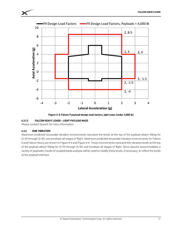
FALCON USER’S GUIDE F9 Design Load Factors F9 Design Load Factors, Payloads < 4,000 lb 10 2, 8.5 8 ) 6 g ( 2, 4 3, 4 n 4 io t a r le 2 e c Ac l 0 ia Ax-2 3, -1.5 2, -1.5 -4 2, -4 -6 -4 -3 -2 -1 0 1 2 3 4 Lateral Acceleration (g) Figure 4-2: Falcon 9 payload design load factors, light mass (under 4,000 lb) 4.3.1.3 FALCON HEAVY LOADS – LIGHT PAYLOAD MASS Please contact SpaceX for more information. 4.3.2 SINE VIBRATION Maximum predicted sinusoidal vibration environments represent the levels at the top of the payload attach fitting for Q=20 through Q=50, and envelope all stages of flight. Maximum predicted sinusoidal vibration environments for Falcon 9 and Falcon Heavy are shown in Figure 4-3 and Figure 4-4. These environments represent the vibration levels at the top of the payload attach fitting for Q=20 through Q=50, and envelope all stages of flight. Since SpaceX accommodates a variety of payloads, results of coupled loads analysis will be used to modify these levels, if necessary, to reflect the levels at the payload interface. © Space Exploration Technologies Corp. All rights reserved. 17
 SPACEX FALCON USER’S GUIDE Page 20 Page 22