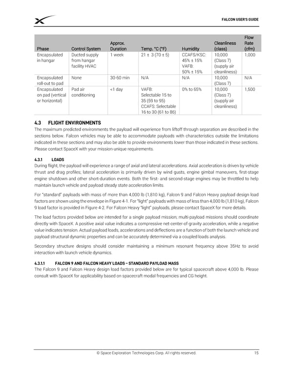
FALCON USER’S GUIDE Flow Approx. Cleanliness Rate Phase Control System Duration Temp. °C (°F) Humidity (class) (cfm) Encapsulated Ducted supply 1 week 21 ± 3 (70 ± 5) CCAFS/KSC: 10,000 1,000 in hangar from hangar 45% ± 15% (Class 7) facility HVAC VAFB: (supply air 50% ± 15% cleanliness) Encapsulated None 30-60 min N/A N/A 10,000 N/A roll-out to pad (Class 7) Encapsulated Pad air <1 day VAFB: 0% to 65% 10,000 1,500 on pad (vertical conditioning Selectable 15 to (Class 7) or horizontal) 35 (59 to 95) (supply air CCAFS: Selectable cleanliness) 16 to 30 (61 to 86) FLIGHT ENVIRONMENTS The maximum predicted environments the payload will experience from liftoff through separation are described in the sections below. Falcon vehicles may be able to accommodate payloads with characteristics outside the limitations indicated in these sections and may also be able to provide environments lower than those indicated in these sections. Please contact SpaceX with your mission-unique requirements. 4.3.1 LOADS During flight, the payload will experience a range of axial and lateral accelerations. Axial acceleration is driven by vehicle thrust and drag profiles; lateral acceleration is primarily driven by wind gusts, engine gimbal maneuvers, first-stage engine shutdown and other short-duration events. Both the first- and second-stage engines may be throttled to help maintain launch vehicle and payload steady state acceleration limits. For “standard” payloads with mass of more than 4,000 lb (1,810 kg), Falcon 9 and Falcon Heavy payload design load factors are shown using the envelope in Figure 4-1. For “light” payloads with mass of less than 4,000 lb (1,810 kg), Falcon 9 load factor is provided in Figure 4-2. For Falcon Heavy “light” payloads, please contact SpaceX for more details. The load factors provided below are intended for a single payload mission; multi-payload missions should coordinate directly with SpaceX. A positive axial value indicates a compressive net-center-of-gravity acceleration, while a negative value indicates tension. Actual payload loads, accelerations and deflections are a function of both the launch vehicle and payload structural dynamic properties and can be accurately determined via a coupled loads analysis. Secondary structure designs should consider maintaining a minimum resonant frequency above 35Hz to avoid interaction with launch vehicle dynamics. 4.3.1.1 FALCON 9 AND FALCON HEAVY LOADS – STANDARD PAYLOAD MASS The Falcon 9 and Falcon Heavy design load factors provided below are for typical spacecraft above 4,000 lb. Please consult with SpaceX for applicability based on spacecraft modal frequencies and CG height. © Space Exploration Technologies Corp. All rights reserved. 15
 SPACEX FALCON USER’S GUIDE Page 18 Page 20